Introduction
This is the Yocto BSP page for Sparrow Hawk.
Software Version List
| Software | Version |
|---|---|
| Yocto Project | 5.0.16 |
| Linux kernel | 6.18.20 |
| U-Boot | 2026.04 |
| Arm Trusted Firmware | 2.14.0 |
How to Startup
If you want to download OS image, please start 3.1.1. Downloading OS image.
If you want to build OS image, please start 3.1.2. Building OS image.
Preparation of the software
Downloading OS image
Download the OS image from GitHub
- BSP(either of the following BSP)
- In case of BSP: core-image-minimal-sparrow-hawk.rootfs.wic.gz
- For Linux users, you can download the OS image using the following command.
wget -c https://github.com/rcar-community/meta-sparrow-hawk/releases/download/v2026-04-13/core-image-minimal-sparrow-hawk.rootfs.wic.gz
- For Linux users, you can download the OS image using the following command.
- In case of BSP + 3D Graphics: core-image-weston-sparrow-hawk.rootfs.wic.gz
- For Linux users, you can download the OS image using the following command.
wget -c https://github.com/rcar-community/meta-sparrow-hawk/releases/download/v2026-04-13/core-image-weston-sparrow-hawk.rootfs.wic.gz
- For Linux users, you can download the OS image using the following command.
- In case of BSP: core-image-minimal-sparrow-hawk.rootfs.wic.gz
Next, jump to 3.2. How to flash.
Building OS image
git clone https://github.com/rcar-community/meta-sparrow-hawk -b scarthgap
cd meta-sparrow-hawk
In case of BSP:
./build.sh
You can find core-image-minimal-sparrow-hawk.rootfs.wic.gz in the following directory.
ls ./build/build-sparrow-hawk/tmp/deploy/images/sparrow-hawk/
In case of BSP + 3D Graphics:
./build.sh --weston
You can find core-image-weston-sparrow-hawk.rootfs.wic.gz in the following directory.
ls ./build/build-sparrow-hawk/tmp/deploy/images/sparrow-hawk/
Next, jump to 3.2. How to flash.
How to flash
Flashing OS image into microSD card
- Linux case
- In case of BSP:
gzip -cd core-image-minimal-sparrow-hawk.rootfs.wic.gz | sudo dd of=<device file> bs=1M status=progress && syncex) gzip -cd core-image-minimal-sparrow-hawk.rootfs.wic.gz | sudo dd of=/dev/sdi bs=1M status=progress && sync
- In case of BSP + 3D Graphics
gzip -cd core-image-weston-sparrow-hawk.rootfs.wic.gz | sudo dd of=<device file> bs=1M status=progress && syncex) gzip -cd core-image-weston-sparrow-hawk.rootfs.wic.gz | sudo dd of=/dev/sdi bs=1M status=progress && sync
- In case of BSP:
- Windows case
- Extract gzip image using 7zip or similer software.
- Flash extracted image into microSD card using Etcher, win disk imager, and so on.
Flashing loader
Please update the loader (u-boot) using the loader file (flash.bin) included in the Yocto OS image (rootfs).
- Insert microSD card prepared in Section 3.2.1 into microSD card slot (CN1 ), then power on the Sparrow Hawk board.
- Update the QSPI memory from U-Boot as shown below, then reboot the system.
load mmc 0:1 ${loadaddr} flash.bin && sf probe && sf update ${loadaddr} 0 ${filesize} && reset
Note:
- If flashing fails and U-Boot no longer boots, please try the recovery procedure. Please see 4 of Tips in Sparrow Hawk page.
How to boot
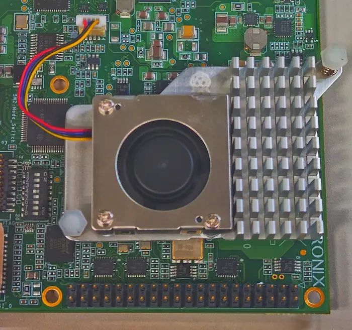
- Ensure that the fan is properly installed.
- Insert the SD card into CN1 which is bottom of the board.
- Open terminal application and open serial device.
- Press SW1 to power on the board.
- After booting U-Boot, please press any key while showing “Hit any key to stop autoboot:” to enter U-Boot shell.
- Input the following command into U-Boot shell and press enter key. If you connect camera and/or display, please choice the following button and input command.
setenv bootcmd "load mmc 0:1 0x58000000 /boot/fitImage && source ${loadaddr}:script" boot - If command and environment is correct, Linux kernel log will output.
- Log in using the following login ID.
- sparrow-hawk login: root
To make the bootcmd set in 5 of 3.3. How to Boot persistent across reboots, run saveenv as shown below.
After saving the environment, reboot the system once. From the next boot onward, this bootcmd will be used automatically, and you can skip 4 and 5 in 3.3. How to Boot.
saveenv
reset  # Execute this only the first time
How to Check Functions
Software support list
| Function | Status(minamal) | Status(weston) |
|---|---|---|
| CAN | Supported | Supported |
| Ethernet | Supported | Supported |
| Audio(Output/Input) | Supported | Supported |
| Display Port | Supported | Supported |
| GPIO | Supported | Supported |
| I2C | Supported | Supported |
| JTAG | Supported | Supported |
| USB3.0 | Supported | Supported |
| UART | Supported | Supported |
| Thermal | Supported | Supported |
| NVMe M.2 SSD | Supported | Supported |
| Pi Camera | Supported | Supported |
| Pi Display | Supported | Supported |
| PCIe Endpoint | Support planned (2026) | Support planned (2026) |
| Pi Active Cooler | Supported | Supported |
| GPU | Not supported | Supported |
| AI Accelerator(CNN-IP) | Support planned (2026) | Support planned (2026) |
| Desktop(GUI) | Not supported | Supported |
Note:
- “Supported”: Function succeeded in the simple test as below.
- “Not supported”: No support plan.
CAN
Loop back
-
- Connect the following pins of CONN2
- Connect Pin1(CAN1L) - Pin2(CAN0L) and Pin5(CAN1H) - Pin6(CAN0H)
- Execute following commands on Linux:
ip link set can0 up type can restart-ms 100 bitrate 1000000 dbitrate 5000000 fd on
ip link set can1 up type can restart-ms 100 bitrate 1000000 dbitrate 5000000 fd on
candump can0 -n 16 &
cangen can1 -I i -L i -D i -f -n 16
candump can1 -n 16 &
cangen can0 -I i -L i -D i -f -n 16
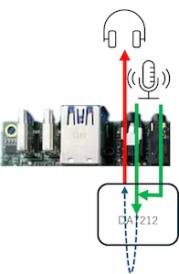
Audio
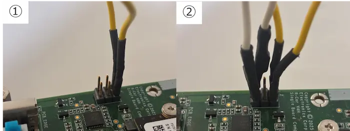
- Audio connector
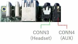
- Sparrow Hawk has two audio input ports. These signals are mixed on the IC and therefore handled as a single-channel input on the board.
- Hardware setup
- Connect headset/earphone/Speaker to CONN3 .
- (if possible) Connect audio output like a smartphone to CONN4
.
- Even if you don’t connect an audio output to CONN4 , you can test.
- Software setup
- Setup(Mix Aux in and Headset mic and setup audio output via CONN3
)
 amixer set "Headphone" 40%
 amixer set "Headphone" on
 amixer set "Mixout Left DAC Left" on
 amixer set "Mixout Right DAC Right" on
 amixer set "Aux" on
 amixer set "Aux" 80%
 amixer set "Mixin PGA" on
 amixer set "Mixin PGA" 50%
 amixer set "ADC" on
 amixer set "ADC" 80%
 amixer set "Mixin Left Aux Left" on
 amixer set "Mixin Right Aux Right" on
 amixer set "Mic 1" on
 amixer set "Mic 1" 80%
 amixer set "Mixin Left Mic 1" on
 amixer set "Mixin Right Mic 1" on
- Setup(Mix Aux in and Headset mic and setup audio output via CONN3
)
- Test function
- Only Playback test (3 times) [CONN3
]
speaker-test -c 2 -l 3 -t wav -W /usr/share/sounds/alsa/ - Only Recording test (5sec) [CONN3
or CONN4
or ‘CONN3
and CONN4
’]
arecord -D hw:0,0 -t wav -d 5 -c 2 -r 48000 -f S16_LE > audio.wav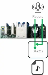
- If you want to check audio.wav, execute following command.
aplay audio.wav
- Recording and Playback test (5sec) [CONN3
or ‘CONN3
+CONN4
’]
arecord -D hw:0,0 -t wav -d 5 -c 2 -r 48000 -f S16_LE | aplay
- Only Playback test (3 times) [CONN3
]
GPIO
Toggle GP2_12(Pin11 on Pin Header)
- Connect LED or Oscilloscope to the board
- ex) LED
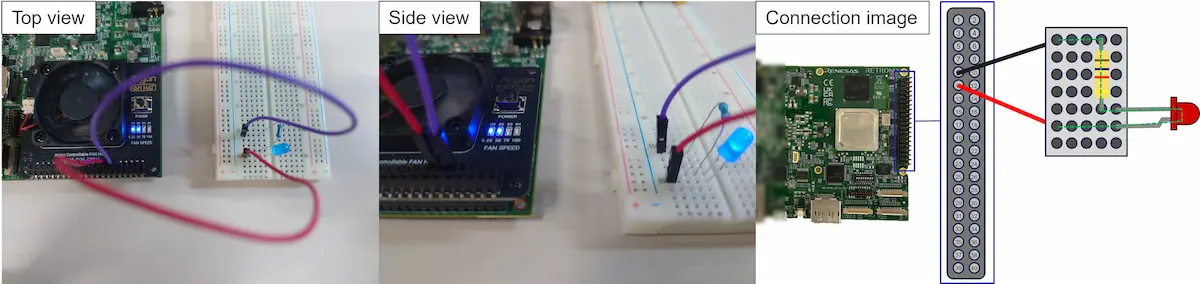
- Please install a resistor to prevent damage to the LED. In the Connection image, it is used a 1kΩ resistor.
- Execute following command
python3 /usr/bin/example-apps/toggle_gpio_GP2_12.py
For more examples, please see also https://github.com/brgl/libgpiod/raw/refs/heads/master/bindings/python/examples
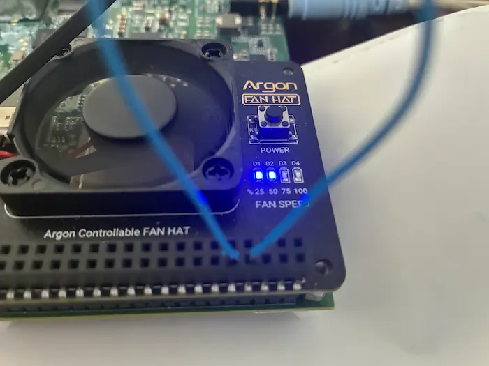
I2C
- Detect I2C device
i2cdetect -y -r 3
i2cdetect -y -r 4
Since I2C bus numbers 3 and 4 are assigned to the External IO, execute the above command.
- I2C pin assignment
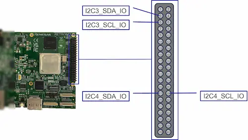
- As an example, output result using Argon FAN HAT and setting ‘setenv bootcmd “load mmc 0:1 0x58000000 /boot/fitImage && bootm 0x58000000#default”’ when How to boot’s step6
- i2cdetect: detect I2C devices on a bus
root@sparrow-hawk:~# i2cdetect -y -r 3 0 1 2 3 4 5 6 7 8 9 a b c d e f 00: -- -- -- -- -- -- -- -- 10: -- -- -- -- -- -- -- -- -- -- 1a -- -- -- -- -- 20: -- -- -- -- -- -- -- -- -- -- -- -- -- -- -- -- 30: -- -- -- -- -- -- -- -- -- -- -- -- -- -- -- -- 40: -- -- -- -- -- -- -- -- -- -- -- -- -- -- -- -- 50: -- -- -- -- -- -- -- -- -- -- -- -- -- -- -- -- 60: -- -- -- -- -- -- -- -- -- -- -- -- -- -- -- -- 70: -- -- -- -- -- -- -- -- root@sparrow-hawk:~# i2cdetect -y -r 4 0 1 2 3 4 5 6 7 8 9 a b c d e f 00: -- -- -- -- -- -- -- -- 10: -- -- -- -- -- -- -- -- -- -- -- -- -- -- -- -- 20: -- -- -- -- -- -- -- -- -- -- -- -- -- -- -- -- 30: -- -- -- -- -- -- -- -- -- -- -- -- -- -- -- -- 40: -- -- -- -- -- -- -- -- -- -- -- -- -- -- -- -- 50: 50 -- -- -- -- -- -- -- -- -- -- -- -- -- -- -- 60: -- -- -- -- -- -- -- -- -- -- -- -- -- -- -- -- 70: -- -- -- -- -- -- -- -- - i2cset: control FAN speed
root@sparrow-hawk:# i2cset -y 3 0x01a 0x00 # 0% root@sparrow-hawk:# i2cset -y 3 0x01a 0x32 # 50% root@sparrow-hawk:# i2cset -y 3 0x01a 0x64 # 100%- Argon FAN HAT: https://argon40.com/en-jp/products/argon-fan-hat
- i2cdetect: detect I2C devices on a bus
- Please search i2c-tools to use other commands(i2cdump, i2cget, i2cset, i2ctransfer).
USB3.0
-
With the power on, connect a USB flash drive to the USB6 port on the board. If “SuperSpeed” is displayed, the test is successful.
- Output example(the upper USB6
port)
[ 74.051911] usb 2-3: new SuperSpeed USB device number 2 using xhci-pci-renesas [ 74.078718] usb-storage 2-3:1.0: USB Mass Storage device detected [ 74.080680] scsi host0: usb-storage 2-3:1.0 [ 75.104448] scsi 0:0:0:0: Direct-Access SanDisk Ultra Fit 1.00 PQ: 0 ANSI: 6 [ 75.117190] sd 0:0:0:0: [sda] 60088320 512-byte logical blocks: (30.8 GB/28.7 GiB) [ 75.120450] sd 0:0:0:0: [sda] Write Protect is off [ 75.122794] sd 0:0:0:0: [sda] Write cache: disabled, read cache: enabled, doesn't support DPO or FUA [ 75.176866] sda: sda1 [ 75.177754] sd 0:0:0:0: [sda] Attached SCSI removable disk - Output example(the lower USB6
port)
[  167.907865] usb 2-4: new SuperSpeed USB device number 3 using xhci-pci-renesas
[  167.939390] usb-storage 2-4:1.0: USB Mass Storage device detected
[  167.940850] scsi host0: usb-storage 2-4:1.0
[  168.960666] scsi 0:0:0:0: Direct-Access     SanDisk  Ultra Fit        1.00 PQ: 0 ANSI: 6
[  168.967661] sd 0:0:0:0: [sda] 60088320 512-byte logical blocks: (30.8 GB/28.7 GiB)
[  168.971146] sd 0:0:0:0: [sda] Write Protect is off
[  168.973359] sd 0:0:0:0: [sda] Write cache: disabled, read cache: enabled, doesn't support DPO or FUA
[  169.026988]  sda: sda1
[  169.027913] sd 0:0:0:0: [sda] Attached SCSI removable disk
- Output example(the upper USB6
port)
UART
Loop back
- Connect UART TX and RX(pin 8 and pin 10) on PinHeader.
- Execute following commands:
stty -F /dev/ttySC2 -echo
cat /dev/ttySC2 &
echo Hello > /dev/ttySC2 && sleep 1
killall cat
Thermal
- Check SoC temperature
cat /sys/class/thermal/thermal_zone*/temp # ex.) 55000 # (Unit is millicelsius => 55.000 °C) -
Thermal throttling
CA76 core temp function ~ 68°C Normal operation 68 ~ 100 °C CPU clock is limited 100 °C System is shutdown forcely -
Measurement point
zone Measurement point thermal_zone0 around Cortex-R52 thermal_zone1 around CNN thermal_zone2 around Cortex-A76 thermal_zone3 around DDR-PHY
NVMe M.2 SSD
Note:
- SATA M.2 SSD is not supported.
- Insert the NVMe into CN5 before powering on.
- The NVMe used for this test is the Samsung 970 EVO Plus.
dmesg | grep nvme- Output example
root@sparrow-hawk:~# dmesg | grep nvme
[    4.738931] nvme nvme0: pci function 0000:01:00.0
[    4.741086] nvme 0000:01:00.0: enabling device (0000 -> 0002)
[    4.745462] nvme nvme0: missing or invalid SUBNQN field.
[    4.747759] nvme nvme0: D3 entry latency set to 8 seconds
[    4.769123] nvme nvme0: 4/0/0 default/read/poll queues
[    4.783049]  nvme0n1: p1
- Output example
Pi Camera
Note:
- Currently, Raspberry Pi Camera V2 and Raspberry Pi Camera V3 is only supported.
Note:
- The Raspberry Pi Camera v3 is currently under development on mainline Linux and libcamera, so at this stage the image may appear dark and features such as auto-focus are not yet supported. In addition, recognition may occasionally fail.
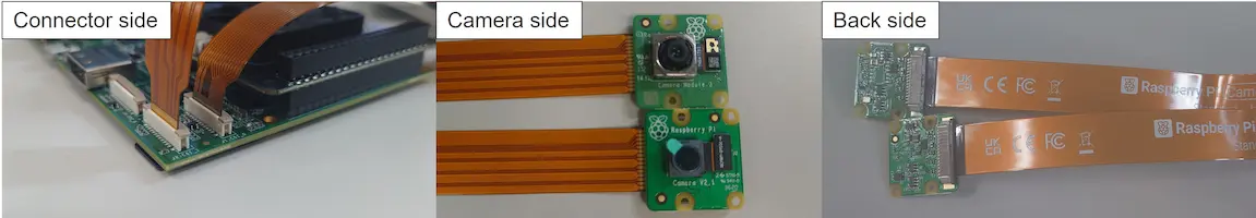
- Connect Raspberry Pi Camera V2 and/or Raspberry Pi Camera V3 to J1
and/or J2
connector.
- The board connector has 22 pin so that you need to prepare pitch convert cable.
- When using the Raspberry Pi Camera V2, the following cable is required.
- Change bootcmd variable on U-Boot shell referring 5 of 3.3. How to boot.
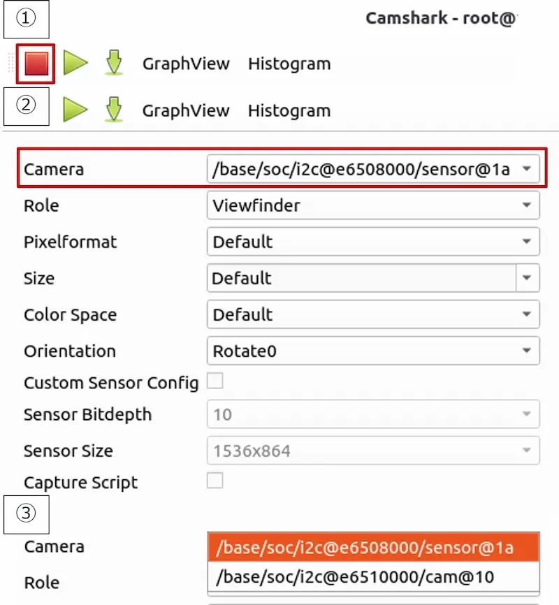
- Test camera
- Camshark test(Need to connect Network and Linux PC)
- Camshark is a gui tool to work remotely with libcamera based cameras.
- Network connection example
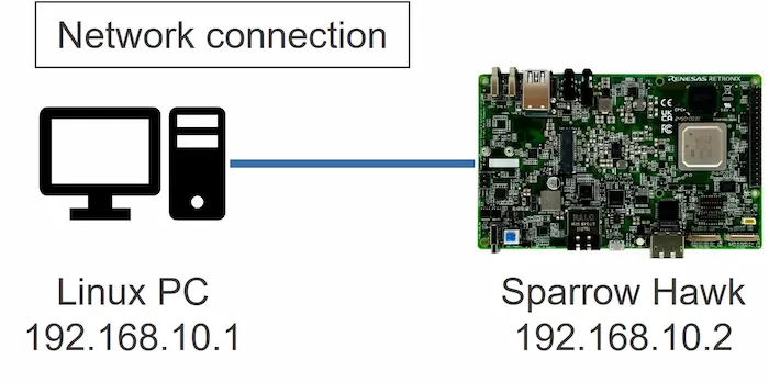
- Please confirm your Sparrow Hawk board IP address on Sparrow Hawk.
ifconfigIf you cannot find inet, please execute following command on Sparrow Hawk.
ifconfig xxx <sparrow_hawk_ip_address>ex) ifconfig end0 192.168.10.2
- Please execute following command on Linux PC.
sudo apt install pipx
pipx install git+https://gitlab.freedesktop.org/camera/camshark.git
camshark root@<sparrow_hawk_ip_address>
ex) camshark root@192.168.10.2
- To switch the camera device when two cameras are connected, follow these steps.
- On-board test(Need to connect Display)
- Camshark test(Need to connect Network and Linux PC)
Pi Display
Note:
- Please perform the following “1. Setup” without connecting the AC adapter to the board (USB1 ).
Note:
- There is a risk of damaging the board or the display, so please connect them with great care.
- Setup
- Connect Raspberry Pi Touch Display 2 cable to the J4 connector.
- Connect the Power (red wire) to pin 2 of CN7 and the Ground (black wire) to pin 6 of CN7 .
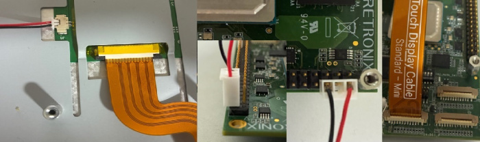
- Change bootcmd variable on U-Boot shell referring 5 of 3.3. How to boot.
- Display will work correctly after changing above.
Pi Active Cooler
-
Connect Raspberry Pi Active Cooler to the J3 connector.
-
- Raspberry Pi Active Cooler: https://www.raspberrypi.com/products/active-cooler/
-
The thermal pad is not aligned with the R-Car V4H Chip. Please reposition the thermal pad to match the location of the R-Car V4H Chip.
-
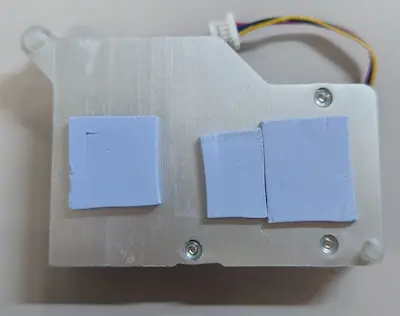
- The thermal pad application method is one example, ensure it is applied to adhere to at least the R-Car V4H chip and DRAM.
-
Manual control of fan speed
echo 2 > /sys/class/hwmon/hwmon4/pwm1_enable
echo 150 > /sys/class/hwmon/hwmon4/pwm1
#1 ~ 255 is acceptable but low speeds are not recommended from thermal perspective.
Tips
- How to flash sdcard without removing the card from the board.
- Preparation: TFTP server on your host PC and network connection between board and your host PC. And copy the gzipped image file into tftp server root.
- ex.) /tftp/core-image-minimal-sparrow-hawk.rootfs.wic.gz
- Execute following command on u-boot shell:
- Note:
- After this operation, all data is erased on the SD card which is inserted in the board.
setenv ethaddr setenv serverip setenv ipaddr tftp ${loadaddr} <image file with gzipped> && gzwrite mmc 0 ${loadaddr} ${filesize}- ex.) tftp ${loadaddr} core-image-minimal-sparrow-hawk.rootfs.wic.gz && gzwrite mmc 0 ${loadaddr} ${filesize}
- Note:
- Preparation: TFTP server on your host PC and network connection between board and your host PC. And copy the gzipped image file into tftp server root.
- How to expand the rootfs
- Please run the following command on your board. Rootfs is expanded to use whole storage.
expand-rootfs.sh
reboot
- Please run the following command on your board. Rootfs is expanded to use whole storage.
Known Issues
| Category | Function | Description | Resolution Date |
|---|---|---|---|
| SW | PCIe | Unstable operation has been observed with some M.2 SSD, and the root cause is currently under investigation. For reference: Stable operation has been confirmed with the Raspberry Pi SSD 256GB (RPI-SC1439). | July 2026 |
| SW | Graphics | OpenCL and Vulkan are present in the GFX package but are not supported. | July 2026 |